When we first started our synth DIY journey here at the Mechlab, two things became very apparent: We didn’t have the soldering chops for strip boards and we didn’t have the patience to wait for custom printed circuit boards. So, we had to come up with an alternative that was cost effective, extensible and immediate. Standard prototyping (proto) boards seemed like the perfect solution. The biggest problem was that no one manufactures proto boards specifically in Eurorack sizes.
We also wanted to reduce the amount of loose wires and panel-mounted components, in favor of PCB-mounted pots, switches and jacks. And we wanted to avoid overly deep modules, because not all of our cases could accommodate them. We looked to commercial module design and set out to find a way to replicate this with available proto boards.
What follows is an overview of our methodology for producing “monolithic” proto boards that are in standard HP widths, and tall enough to PCB mount all the interface components. Like any cat, there’s more than one way to skin it. This is what works for us, and maybe it will help you, too. The proto boards we use come in a variety of sizes, but can be oriented to produce monolithic boards from 4HP all the way up to 20HP. (Click the images to see them in full size.)
1.
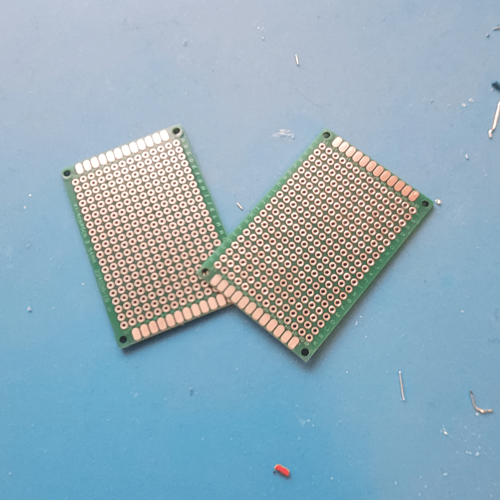
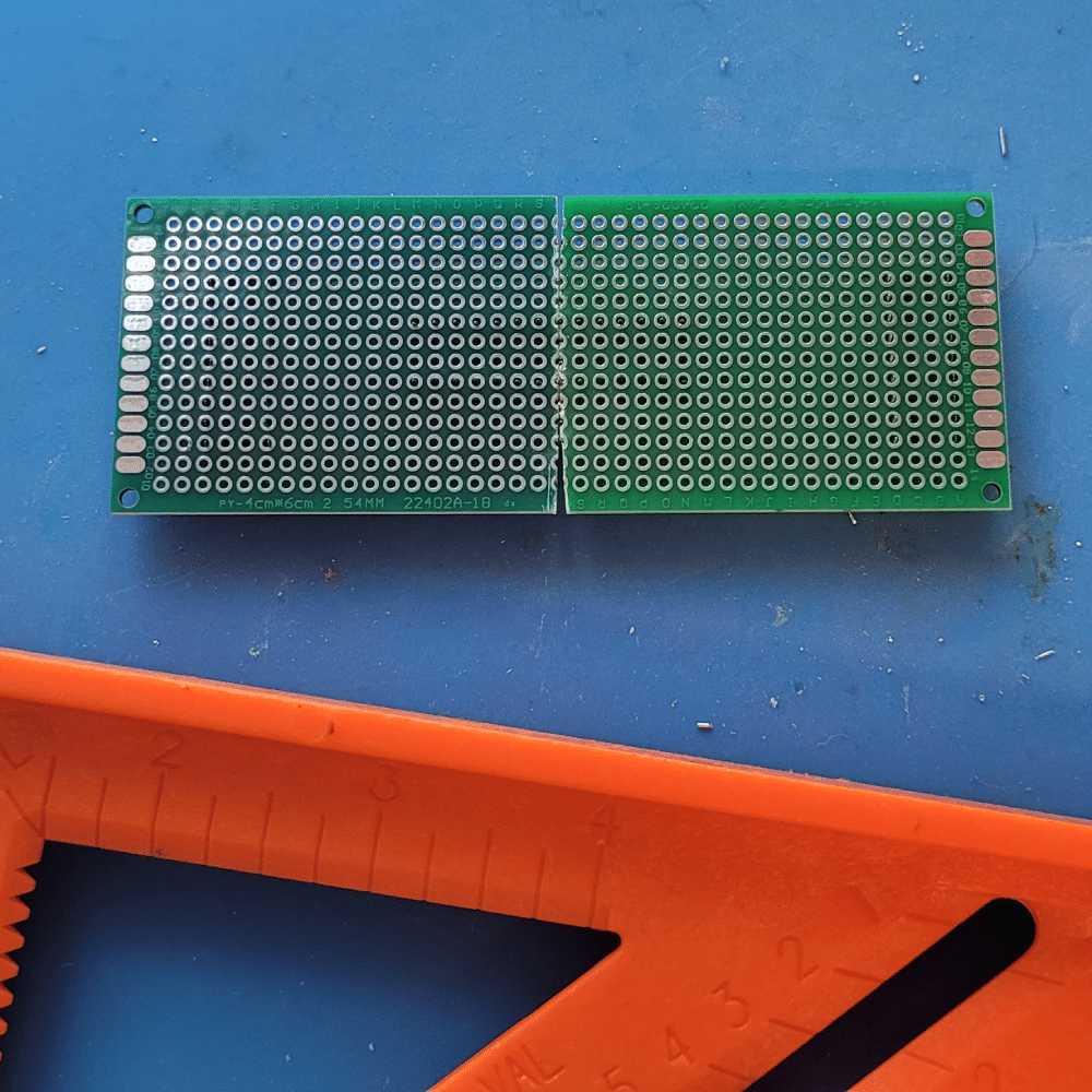
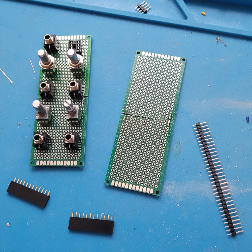
For this demo, we’re using 40mm x 60mm proto boards. We’ll be using them vertically, which is roughly 8HP in width. You could use them horizontally to build a monolithic board in 12HP.
2.
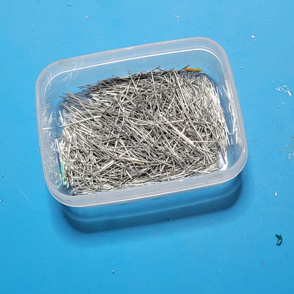
Besides the proto boards, we’ll also need something to bond them together. We save the cut-offs from resistors, capacitors, LEDs, etc. from our builds, and this is a great use case for them. You’ll need 2-3 pieces that are relatively straight and roughly 25mm in length.
3.
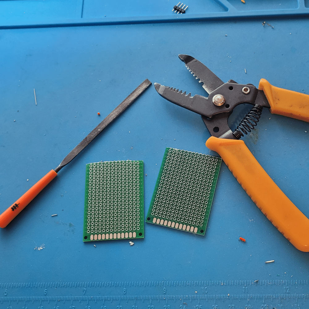
Our cases have roughly 112mm of clearance between the rails, so we want to make sure this board will fit. Fortunately, with the 60mm length, if we cut off one end of each board, at the first row of holes, when they’re joined, they are the perfect height.
We find that a wire stripper works great as a board cutter in this scenario. A small file is useful to have around to clean up the edges where the board breaks.
4.
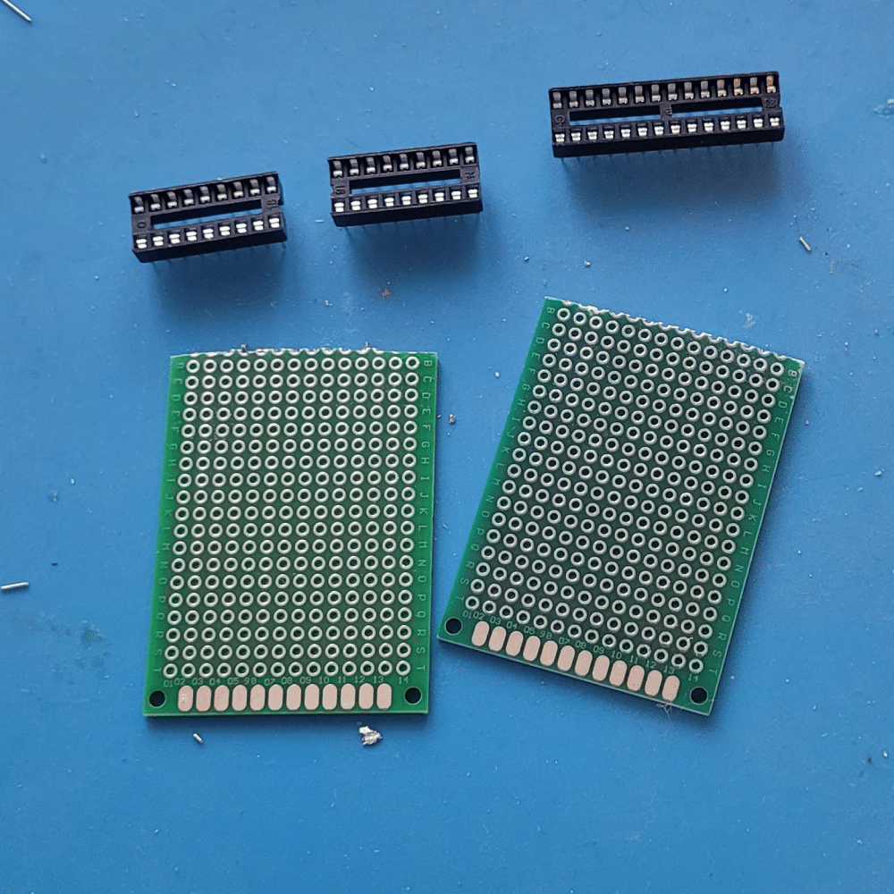
This step might be us being a little persnickety, but we find it easier to work with the final product if the holes are equally spaced across the entire length of the board. Our proto boards have a standard 2.54mm “pitch” (the spacing between the center of one hole and the center of an adjacent hole). To help maintain this pitch, we use empty IC sockets as spacers.
5.
Line up the two boards, with the cut sides facing one another. Place the long IC socket so that it bridges the two boards. This will ensure that the pitch is reasonably consistent, as you move from one board to the next, and will help with placement of components later.
The smaller IC sockets are under the ends of each board, to help keep the boards level.
6.
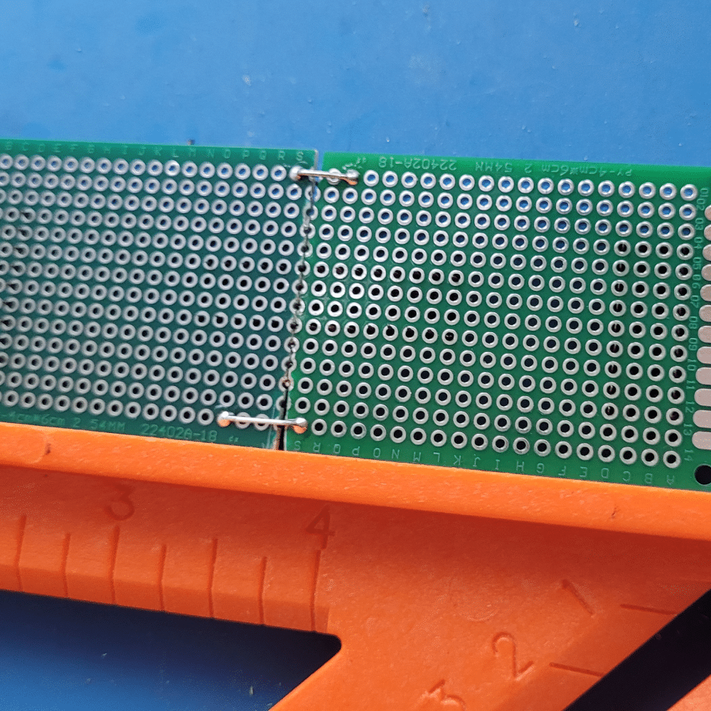
Making sure the edges of the board are straight is a little more important than consistent pitch. This will help maintain the proper width of the module. If the boards are crooked when they’re joined, one end of the module might overhang the faceplate, and make it difficult to install in your case.
Use a straight edge or a speed square to maintain a clean edge. Feed your cut-offs from step 2 through holes on each board, bending the leads down and around, so that they wrap around the front and back of the joint, and create a loop that joins both boards, on both sides.
7.
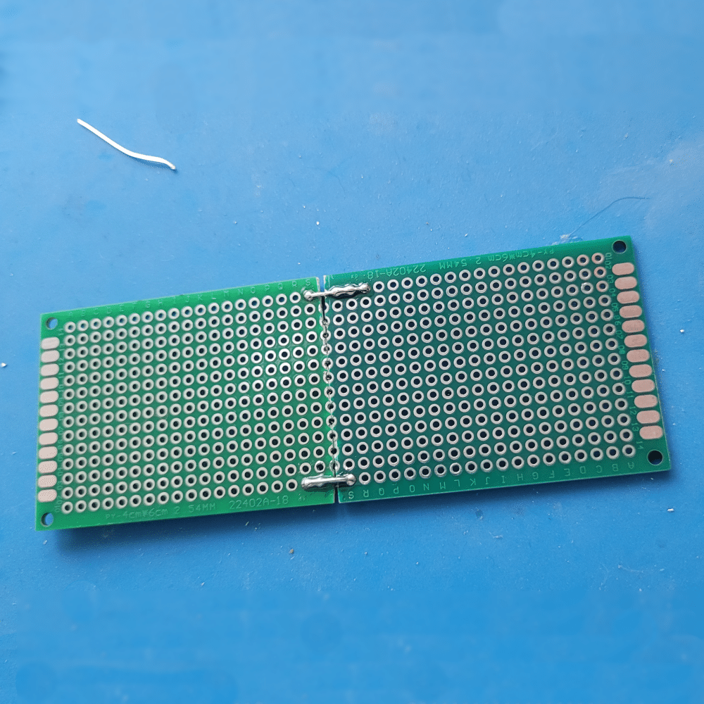
Solder these loops in place, going around both sides of both boards, so that all 8 points (both boards, top and bottom, front and back) are solidly soldered in place. Be sure to use the straight edge when doing so, to maintain a clean edge. Once this is done, you will have a monolithic board.
You might find that it’s still a little flexible at the joint. Typically this gets resolved as the module is built, as there will be other opportunities to run a component lead or two across the joint and reinforce it. You can always add more leads as necessary, to get the rigidity you desire.
Stacked Monolithic Boards
Very few of our modules have a component count low enough that a single monolithic board was sufficient for building the module. Again looking at commercial designs for inspiration, we developed this process for stacking monolithic boards using headers.
1.
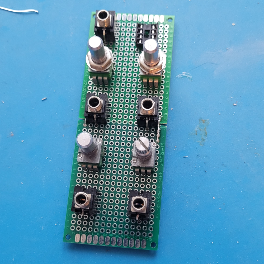
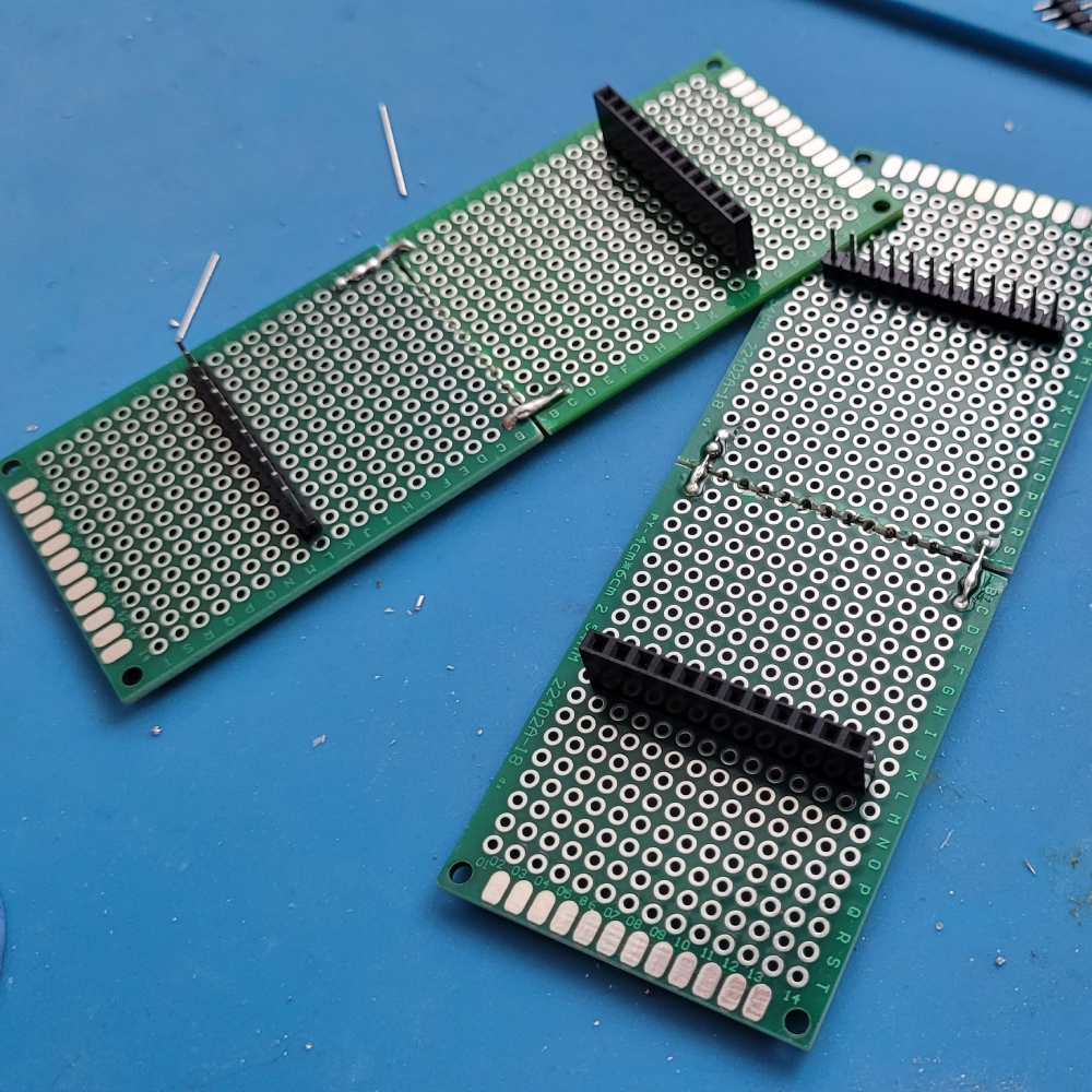
Using the monolithic board from the instructions above (we made another, identical, one off-screen), we’ve laid out where we want to place our interface components. For this module, we have five jacks and four pots–and we found space to squeeze in an 8-pin IC.
Our intention at this stage is to find the optimum placement for each component, then identify empty areas with adequate space for installing and wiring a header. Some of the things we look for are clearance for other components, proximity to the components that need to connect to the other board and ease of access for soldering.
These components shouldn’t be soldered in place yet!
2.
It’s also important to know how many connections you will need to the other board. Count all of the connections, and make sure you select headers that will accommodate those. Don’t forget things like ground for pots and jacks, and power supplies for ICs, LEDs and other active components. We generally try to pick headers that will give us a few extra pins, in case we forgot to count a connection.
3.
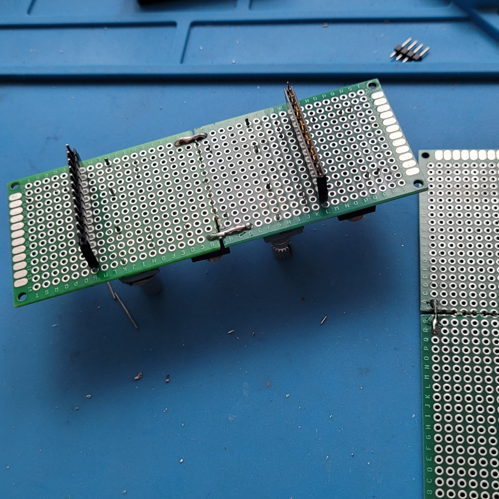
Carefully flip the board over and place your headers in the holes you’ve identified in step 2.
Pro tip: If you’re using multiple headers that have the same orientation and number of pins, we recommend alternating which side is soldered to which board (see the picture in step 5 for an example). This will eliminate the possibility of accidentally plugging the boards in backwards (and potentially routing power to the wrong components).
4.
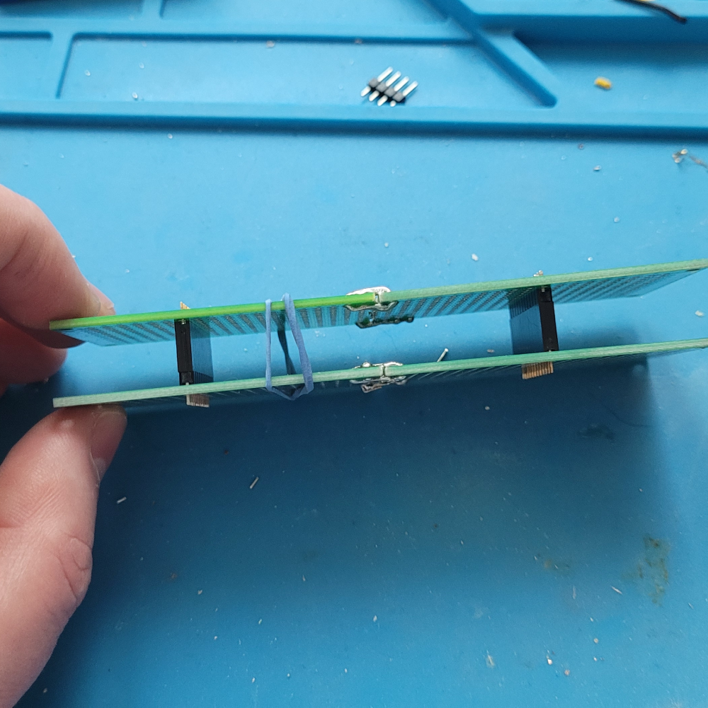
Now place the other board on top of the headers, ensuring that they are in the correct holes and all four sides of both boards line up. We find it helpful to use a rubber band to hold the boards together, so they don’t fall apart during soldering. The interface components are no longer needed, at this stage, and can be removed.
5.
Solder all the pins on both sides. If you’ve alternated the headers as suggested in step 3, it should look like this. You can’t plug the “female” ends into one another, or the “male” ends into one another, so this will ensure you’re always connecting the boards correctly.
Wiring Headers
Well, those headers ain’t gonna wire themselves. There’s a catch, though. Now you have the headers, but the soldered connections are on the front of the board and the interface components are soldered to the back of the board. Here’s how we wire up our headers, so that we can complete those connections.

1.
This will require a handful of cut-offs, like the ones we used in step 6, when creating the first monolithic board. The distance between the header and the component to which it needs to be connected will determine the length of the cut-off lead needed. At a minimum, it will need to be 8-10mm, to get from the front to the back of the board.
Bend a 90 degree turn in the cut-off. The short end should be long enough to securely solder to the pin of the header and allow the long end to fit in the adjacent hole.
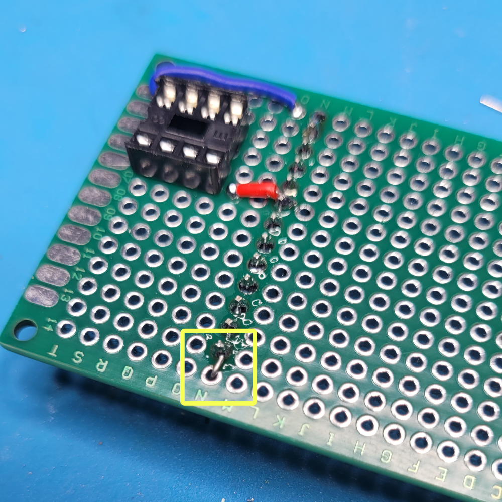
2.
Feed the long end of the cut-off through the desired hole and solder the short end to the pin of the header.
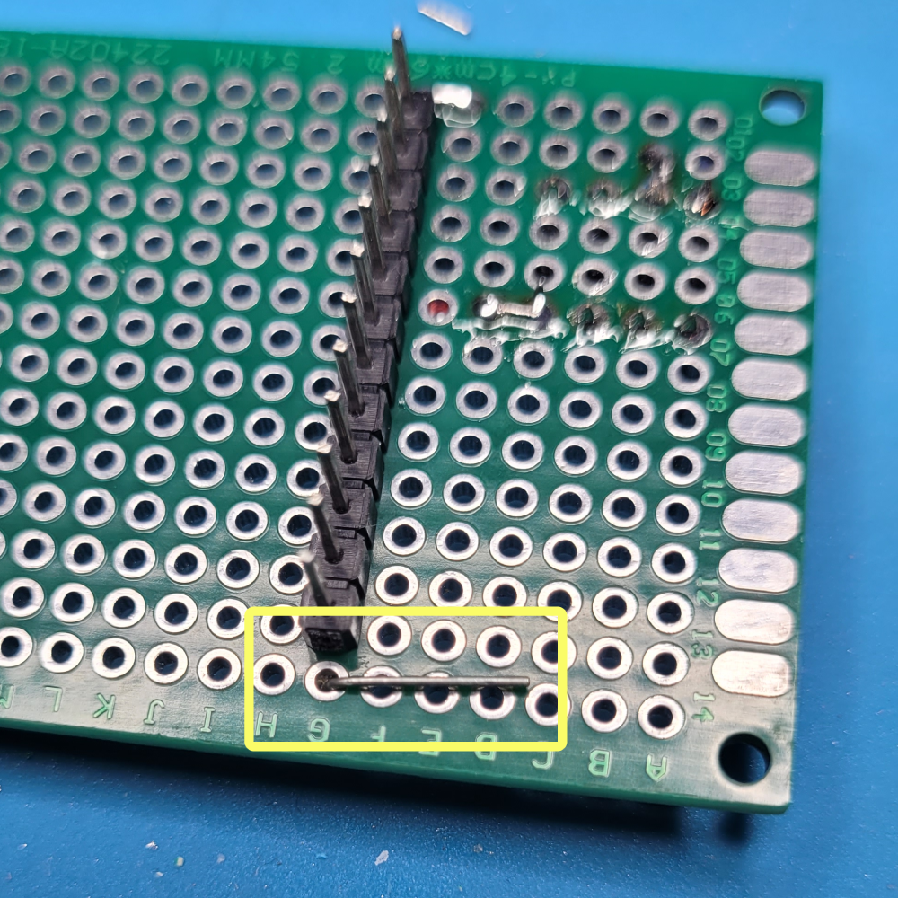
3.
On the bottom of the board, bend the cut-off over so that it becomes a lead. You can solder additional cut-offs to this lead, to route it to the component to which it needs to connect.
Not shown here, but we also recommend soldering the hole that the long end of the cut-off passed though, to provide additional support and security.
Leave a Reply